![[picture of CUI v1.0 board]](http://www.create.ucsb.edu/~dano/CUI/CUIv10small.jpg)
CUI version 1.0
Dan Overholt
U.C. Santa Barbara
Center for Research in Electronic Art Technology
|
CUI version 1.0 Dan Overholt
|
The need for the "CUI"In the Media Arts and Technology program, we explore new metaphors for artistic interactivity that connect the physical world with the virtual realm. We develop new techniques for computing that generate music and visual arts in a myriad of ways; but in order to put forth these techniques, we must create new sensors, and build interfaces that can better grasp their control and generation. The CUI allows us to bind physical processes or actions to corresponding digital expressions.To simplify this process of connecting the real world to the virtual, the CUI provides the necessary electronics to capture sensor input or control actuator output. The CUI comes with a USB port, a power LED, a Reset switch, a Programming switch, and a prototyping area. At the heart of the board is the PIC18F4550, a versatile microcontroller made by Microchip Technologies, Inc. The PIC18F4550 features thirteen A/D inputs, eighteen general I/O ports, and an efficient RISC-like instruction set. The CUI only uses one of the PIC's general I/O ports; the remaining ports are available for user applications to be built in the prototyping area. The total cost of the CUI is around $30 US when built in small quantities.
|
|
About this DocumentThis document is written primarily for anyone who wants to create an interface using the CUI. It is also useful for anyone who wants to understand the process of developing applications for microcontrollers in general, and for Microchip PIC processors in particular.Here's what you'll find in this document:
|
|
AcknowledgementsThe author gratefully acknowledges the support and inspiration from the following people. Curtis Roads, JoAnn Kuchera-Morin, Stephen Travis Pope, George Legrady, and other faculty members of the MAT, ART, and CS departments.Wesley Smith and Rama Hoetzlein kept things moving through the formative stage of the CUI project. They volunteered many hours to help develop the code and teach other students about PICs and basic electronic circuitry. All of the students involved in the Media Interface Technology course have made this a fun project. And thanks to Robert Poor for the web page layout, taken from his iRX page. |
|
|
|
1.0 |
OverviewWhat you get out of the CUI depends on what you put into it. It's unlikely that there will be any "pre-canned" configurations that exactly suit your needs--you will generally need to add custom hardware on the board and create a PIC program specifically for your application. But that's the fun part of the process! To give you a taste of what's possible with a PIC and CUI board,
here are some projects that people could create using the CUI (or
should be able to create):
|
Overview of the Development ProcessThis section briefly describes the steps you'll need to take to create your very own CUI application.Ready...The first step is to make sure you have all the materials at hand. You'll need both some hardware and some software:
Set...It's unlikely that you will find any pre-compiled firmware for the PIC and CUI that will do exactly what you want. Usually, you'll need to write a program for the PIC (or perhaps modify an existing one). In most cases, you'll also be adding extra components and wires to the CUI board.The CUI was meant to be customized, so go for it!
Go...Creating and downloading code for the PIC is a five step process, described in the picture and in the text below.
|
|
|
|
2.0 |
Guided Tour of the CUI "0.9" DIY approach![[image: CUI 0.9 board]](CreateUSBprototype.jpg)
This section describes the layout and schematic of the CUI 0.9. It will show you where each component is located, and describes what each component does. Figure 2 shows the layout of the components on the CUI 0.9 board, Figure 3 is the schematic for the board. 2.1 Layout of the CUI 0.9 |
![[image: layout of the CUI 0.9 board]](CUI0.9topAnnotated.jpg)
|
|
|
Note that this layout is slightly out of date and needs to be corrected. The resistors above the ICSP (In-Circuit Serial Programming) Connector are not needed, and the pull-up resistors for the Reset and Program buttons values have changed. The 100uF capacitor is not shown, and you just barely see the 15pF capacitors next to the 20 MHz crystal. The bypass capacitors and VUSB capacitor are not labelled in the photo. 2.2 Schematic of the CUI 0.9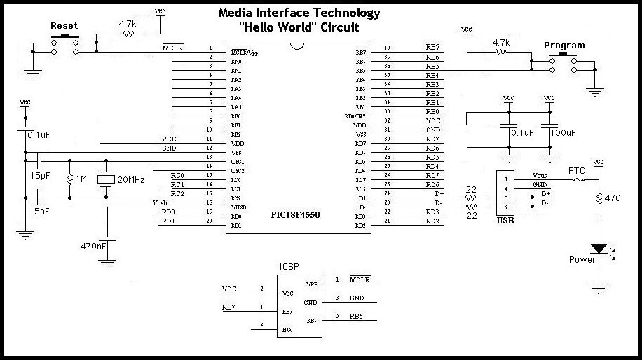
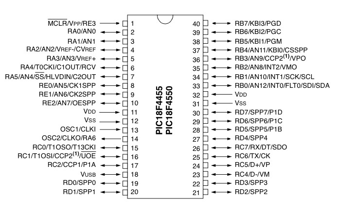
Figure 3: Schematic of the CUI 0.9 board - (if you're looking for the schematic of the CUI v1.0 board, it is here and the layout here - there are no changes to the base v0.9 circuit, just additions for the headers and prototyping area) 2.3 Component Description2.3.1 USB ConnectorThe USB Connector is a standard "type B" connector. You can plug any "A-to-B" type cable into it, with other end (the flat connector) going to your computer. There are four connections in a USB cable, two of which supply power to the CUI board, while the other two are the communications lines D+ and D-. This is how information is transferred between the host computer and the PIC both when it is being programmed, and while your firmware sends or receives data with the computer if it is a HID application.2.3.2 Power indicatorWhen USB power is applied, the LED is lit. Note that some CUI circuits may not be able to use USB power if they require more than 100mA of current (this is maximum amount of current that is allowed to be drawn from a single USB port). The alternative is to use a standard voltage regulator such as the LM7805, which then provides +5V at 1000mA (1Amp) from a 7-15VDC "wall wart" power supply. An LM7805 can also let you use a 9V battery connector and power the CUI 0.9 from a standard 9V battery for stand-alone applications.2.3.4 Push buttons "Reset" and "Program"The two buttons on the CUI are used during the process of programming your application. They are labelled "Reset" and "Program" - pushing the Reset button is the equivalent of unplugging the USB cable and plugging it back in (which should cause your computer to recognize the CUI and initialize the corresponding driver). If you push the Reset button while holding down the Program button, the CUI will enter the bootloader mode, which will allow a new application to be loaded into the PIC (via the PDFSUSB.EXE program).2.3.5 ICSP ConnectorThe In-Circuit Serial Programming (ICSP) connector is only used one time for each new CUI board. It allows the bootloader to be burned into the PIC's memory via a standard PIC programmer such as Microchip's ICD2. Section 5 details the process of installing the bootloader.2.3.6 PIC I/O PortsAll of the unused pins of the PIC on the CUI board are user I/O ports that can be connected to custom circuit extensions along with power, ground, etc. You can solder some "Molex headers" into the board if you want a simple means to temporarily connect wires and components to your CUI board. The layout of the I/O ports follows the pinout of the PIC18F4550 as shown below. A description of the characteristics of each I/O is in Section 4.
Figure 5: PIC I/O Ports 2.3.7 PIC18F4550The PIC is the heart of the board. It's a programmable microcontroller with 32Kbytes of flash program memory and 2kbytes of general purpose SRAM. It has 13 A/D inputs and 18 general purpose I/O ports. On the CUI board, one of the general purpose I/O pins is dedicated to the "program" button to enter bootloading mode. You can use the remaining ports for anything you wish.2.3.8 20MHz Crystal oscillatorThis particular part has the job of providing a clock signal to the PIC, and it's corresponding 15pF capacitors and 1Mohm resistor are required to make it oscillate properly. Crystals with other frequencies are available, but 20MHz was chosen since it's the same as the evaluation board from Microchip.2.3.9 PTC FuseThis part protects your computer and the CUI board from damage in the event of a short circuit or over-current condition. It is a Positive Temperature Coefficient (PTC) type fuse, which means that it is resettable, and will automatically allow your circuit to work again once the short circuit is fixed. |
|
|
|
|
3.0 |
Building a CUI 0.9This section details the process of building complete CUI 0.9 boards from scratch:
3.1 Purchasing the componentsAll of the components are included in the lab kit for class, or they are available from Digi-Key, Mouser, or other mail-order electronics parts suppliers. While those mentioned are not always the cheapest, they have most all of the compoents in stock, take online card orders, and will get you your parts however fast you want them (FedEx, etc). If you have more time than money on your hands, you may be able to shop around and get a better price on some of the parts shown here. Additional parts, such as a 7805 voltage regulator or special sensors you wish to use can also be acquired from Digi-Key, Mouser, etc., or possibly at a local store such as Marvac or Radio Shack if the component is not too esoteric.The following lists details the parts required to build a single CUI board. The first column specifies component name, and the Mouser part # is shown in the second column (or other alternatives if Mouser does not stock them). When possible, I've shown Mouser's prices (as of April 2005), but these reflect pricing when purchasing supplies for more than just one CUI (10 or more). If you would like the list of parts in Excel format, this is the bill of materials spreadsheet. |
![[image: bill of materials for CUI board]](CUIbomBeta.jpg)
|
|
3.2 Soldering the components onto the boardSoldering the components onto the CUI board isn't difficult. Assuming you've already had basic experience with soldering, here are some hints:The only components that don't care which way they're inserted are the resistors, the ceramic capacitors (the 100uF is an electrolytic cap so it needs to be oriented with its minus leg to ground), and the crystal oscillator. For all others, use the schematic diagram as a guide. Note that for the LED, the longer wire is the positive '+' side. There are a few components that should be placed as close as possible to the PIC, should you decide to change the layout on your board. These are the 0.1uF bypass capacitors, and the 20MHz crystal oscillator - the bypass capacitors help keep the power supply clean, and the crystal needs to be close to ensure a good clock signal is provided to the PIC (shorter traces provide lower inductance for this high frequency signal). To keep components from falling out while you're soldering others (since you have to flip the board over to solder the leads) it may help to work from the "shortest" to the "tallest" components. Be careful not to overheat the sensitive components during soldering, especially the PTC, and the smaller capacitors.
|
|
|
|
||||||||||||||||||||||||||||||||||||||||||||||||||||||||||||||||||||||||||||||||||||||||||||||
4.0 |
Developing an ApplicationThe steps towards creating your PIC application are straightforward and have been outlined in Section 2. In this section, we jump into the details.4.1 Not all I/O Ports are created EqualThe PIC18F4550 has thirteen A/D ports: RA0 - RA3, RA5, RB0 - RB4, and RE0 - RE2. Among these, the order is somewhat random so be sure to look up the correct pin number in the data sheet. (Note: you can still use these pins as general purpose I/O pins if you're willing to give up A/D converter inputs). Some ports have particular traits that may make them more or less suited for your particular application. The following table summarizes the differences; for the full scoop, consult the Microchip data sheets.Except as noted, all ports support TTL levels and are bi-directional under program control.
The CUI 0.9 board leaves many of these pins entirely untouched. This makes it possible to build your own circuit around the microcontroller. Port B, when used as inputs, can be programmed in software for internal weak pull-ups (this is useful when connecting simple switches or buttons to the PIC). 4.2 C versus Assembly codeWhenever possible, program in C instead of in assembly language. You'll find the development and maintenance of firmware programs to be much faster and easier. However, there are some times when you may still need to program in assembly (or put sections of assembly "in-line" using the #asm construct):
4.3 CompilersThere are a number of different PIC C compilers available. Till now, we have stuck with C18 from Microchip, but there are also CCS, Hitech, and GCC compilers available. The C18 compiler comes with good examples, which is one benefit, but the 60 day student trial is possibly a hassle. However, we have yet to run into any real problems with this. As for assemblers, it's easiest just to use MPASM, the free PIC assembler from Microchip that's built into MPLAB.4.4 Burning your program into the PICThe wonderful thing about a bootloader is that you don't need to have a device programmer to load new code into your PIC. In a few rare circumstances though, you may want one anyway. Though there are many PIC programmers available, we've settled on the ICD2 programmer from Olimex. If needed, it can purchased online via Spark Fun Electronics, and it has proven to be robust and reliable so far, with upgrades for the programmer after they introduce new chips a non-issue (it emulates a "real" ICD2 as far as MPLAB is concerned).The easiest way to download your bootloader into the PIC is through the ICD2 programmer menus in MPLAB. 4.5 PIC SimulatorsA PIC simulator lets you step through your program, set breakpoints, examine registers; some of these things can be done with the real chip as well if you have the ICD2 (In-Circuit Debugger) hooked up to your CUI board. If you don't have an ICD2, the simulator built into MPLAB can give good results.
|
|
|
|
5.0 |
Debugging Tips & TechniquesFollowing is a random collection of tips, techniques, art and lore. Your mileage may vary, but little things such as these can sometimes be the difference between success and complete lunacy.5.1 First principlesWhen you write your program, it is always a good idea to make an LED blink, just to indicate that the chip is alive and running. Obviously, this cannot be the power LED, but another LED wired up to a Digital I/O pin that is configured as an output. So assume you've written your program, compiled and loaded the
code, and powered up your CUI. And the LED doesn't blink. Now what?
5.2 Debugging
5.3 Burning the bootloader
Pre-made, ready-to-use CUI v1.0Feel free to email me if you're interested in a getting a pre-built/bootloaded CUI v1.0 for 50 Euros. It comes ready to use with Max/MSP/Jitter, SuperCollider, or any other program that receives USB HID data - just hook up your own sensors to the 13 analog inputs (10-bit resolution) and buttons/switches to the digital inputs, etc... You can also get ready made sensors from the phidgets website, and of course you can re-program it using the bootloader (no need for a PIC programmer), and use the prototyping area to do whatever you want.
CUI v1.0 can be custom-ordered with Bluetooth for wireless functionality (works with Max/MSP and Pd, same features as wired version), powered by rechargeable Li-Ion battery! Also, here is a forum that can be used by those working with the CUI: USB Development forum at sparkfun Plus a couple of mailing lists for those working with the CUI: CUI-users subscribe here and CUI-dev subscribe here Links to example Max/MSP/Jitter, Pd, and SuperCollider Patches: USB CUI for Macintosh USB CUI for Windows Bluetooth CUI for Macintosh and Windows Bluetooth CUI for PD USB CUI for for Max4.6 - on intel Macs with Max/MSP 4.6, the [hi] object seems to have changed, this firmware update and corresponding test patch resolves the problem. Also includes "CUI IO v1.0" firmware for compatibility with [hidio] object for both Max and Pd (currently in progress 17 January 2007). SuperCollider3 HIDControl - port of Jan truzschler's HIDControl Ugen to intel Macs - also removes the autoscaling to avoid clicks. Here are some new and useful tools for the CUI made by users! CUIOSC by MarkDavid Hosale - a stand alone OS X program that converts the CUI's USB input to OSC (Open Sound Control). Boot Down by Craig Schimmel - a CUI bootloader utility for OS X that allows firmware updates on Macintosh! 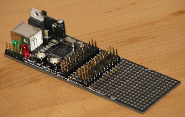
From May 2008, all pre-made CUI boards are black as shown above, with the new PIC18F4553 that has an increased resolution 12-bit ADC! They also natively support Open Sound Control (OSC) and MIDI-over-USB functionality in addition to the default HID firmware. Example firmware and corresponding Max5, Pure Data, and SuperCollider, ChucK, etc. patches coming soon... The price for the new black CUI boards is 50 Euros plus shipping (from Denmark). Email me to get a quote - payment is through PayPal (can be done online with a credit card even if you don't have a PayPal account), and invoices can be sent in PDF format. The "CUIduino" is born - an Arduino in the prototyping area of a CUI, see here for instructions! 
The CUIduino has the potential to allow your Arduino projects to show up as a true HID device (mouse/keyboard/gamepad, etc), or many other device types (see some below), unlocking Arduino from the tyranny of the FTDI USB-serial converter chip. But what is this blasphemy, having a PIC and an AVR chip on the same board, you ask? The answer may lie in this PIC vs AVR smackdown which points out - at the bottom of the page - that PICs have had hardware USB support for some time now. While the CUI came out around the same time as the Arduino (2005), it was the only one to feature true USB - nonetheless, the Arduino became popular due to its easy development environment and availbility. The Arduino community is a wonderful thing - an open source ideal that the CUI has always shared ... and now you can have your cake and eat it too with the CUIduino! The CUI now speaks OSC (Open Sound Control) natively, thanks to CNMAT! Get "µOSC" here... The CUI also now speaks MIDI-over-USB natively, this bypasses the old-skool MIDI baud-rate limit of 31.25KHz, since the concept of buad rate is completely obfuscated with MIDI-over-USB. Additionally, this firmware (for the 18F4553-based CUIs) sends all the analog input pins as pitch-bend type data (using all 12 bits of the ADC converter) along side note-on/note-off data from the digital input pins. Thus, many of the problems with the original MIDI specification (low bandwidth, limited resolution) are addressed. A compiled hex file for the CUI and an example Max5 patch for receiving the data included in the zip file - get it here. Many thanks to http://omino.com/ for the base firmware - it currently works great on OS X, not so great on Windows, and hasn't really been tested on Linux yet. Finally, an updated version of the original HID game-controller type CUI firmware (much improved, using interrupts) is here, and you can find the MPLAB source project files here. |
|
|
|
App A |
Related LinksPublications about the CUI
USB Info
Host Info
|
![[img: foo.c->MPLAB/C18.EXE->foo.hex->CUI]](process.jpg)